NA v1.1.4: Difference between revisions
| Line 51: | Line 51: | ||
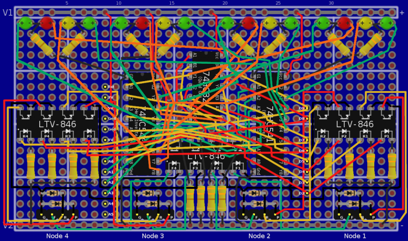
|colspan="2"|[[Image:na_v1.1.4_full_build_04.png|thumb|800px|center|Board Layout preview using the PADS-4 prototyping board. All the wiring visible. It's a mess, you really need to see the layered version to be able to follow the wiring.]] | |colspan="2"|[[Image:na_v1.1.4_full_build_04.png|thumb|800px|center|Board Layout preview using the PADS-4 prototyping board. All the wiring visible. It's a mess, you really need to see the layered version to be able to follow the wiring.]] | ||
|} | |} | ||
== Case == | |||
* [[Possible Cases]] | |||
{{na_footer}} | {{na_footer}} | ||
Latest revision as of 05:38, 7 April 2010
|
Node Assassin :: NA v1.1.4 |

|
This version of the Node Assassin hardware implements an independent sense circuit which is to be fed from the nodes power LED line. This is used to verify when a node truly has died. This brings Node Assassin to fully support all of the fence daemon's recommended features.
Part List
- 1x Arduino: Duemilanova
- 1x Network Shield: Assembled
- 1x Protoboard: Lab-Easy PADS-4 (or equivalent)
- 3x Optoisolators: LTV-846 (4 circuits/chip)
- 1x Inverter: 74HC540 (8-channel high-power; drives 8x 10mA LED)
- 1x Buffer: 74HC541 (8-channel high-power; drives 8x 10mA LED)
- 1x OR-Gate: 74HC32 (Quad OR Gate)
- 8x Diode: 1N4148 (Diode)
Either:
- 4x Green LEDs (max 10mA)
- 4x Red LEDs (max 10mA)
OR (harder to find)
- 4x Bicolour LEDs: 350-1839-ND (Bicolour Red/Green, 2x1 stack, common cathode, max 10mA/colour)
Cables
You will need to make custom cables with pass through connectors to properly use Node Assassin. The only real requirement is that the connector attaching to the Node Assassin be 1x4 wide, 2.54 pitch female connector. Personally, I like to run a common ground to the power button connector and then fan it out to the other two connectors. Each distal connector needs to have a male pass-through connector so that you can still plug in the case cables.
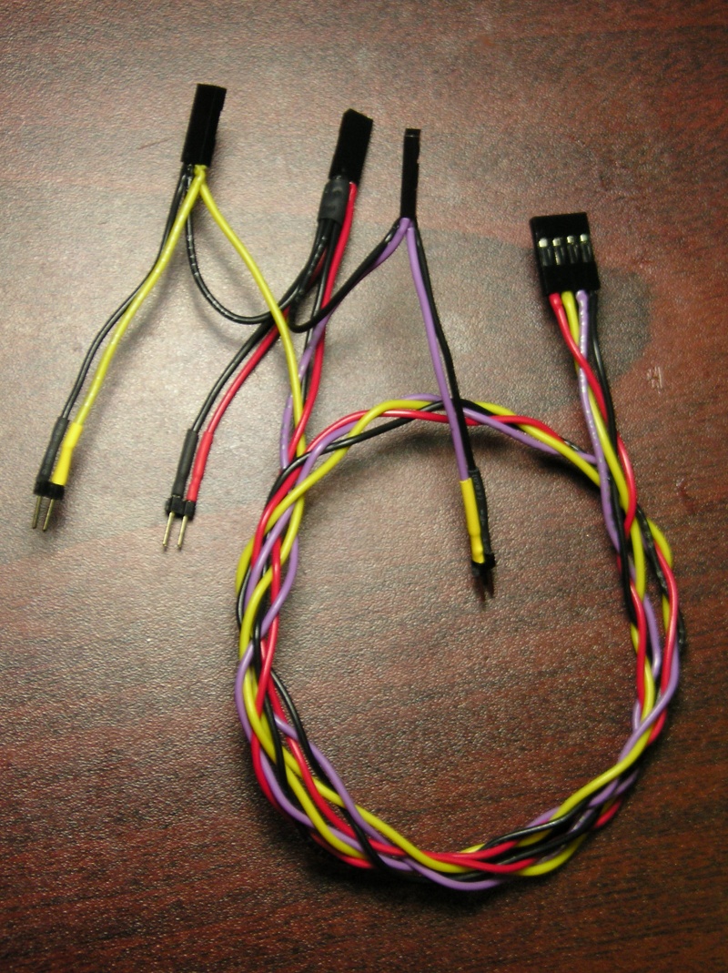
Note that if your motherboard uses the three-pin wide header for the power LED, just use a knife tip to swap out the connector on the NA cable with the chassis cable.
Diagrams
Circuit
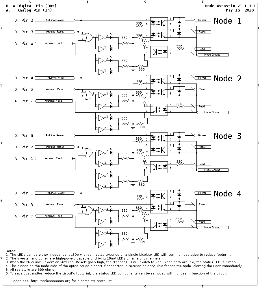
PADS-4 Layout
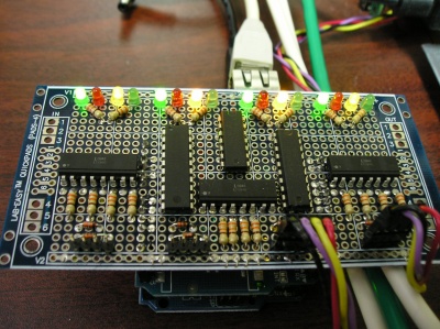
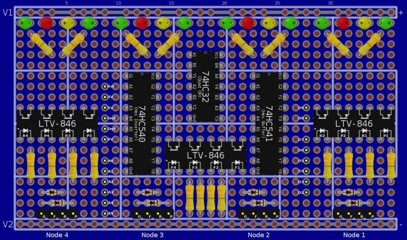
This is the version of the board without the wiring and with minimal wiring (missing the cross connects). Here is an XCF formatted copy of the board layout with all the wiring on different layers. Open it in The GIMP and you can then selectively hide or show layers to see how the wiring works.
Case
| Input, advice, complaints and meanderings all welcome! | ||||
| Digimer | digimer@alteeve.ca | https://alteeve.ca/w | legal stuff: | |
| All info is provided "As-Is". Do not use anything here unless you are willing and able to take resposibility for your own actions. © 1997-2013 | ||||
| Naming credits go to Christopher Olah! | ||||
| In memory of Kettle, Tonia, Josh, Leah and Harvey. In special memory of Hannah, Jack and Riley. | ||||
